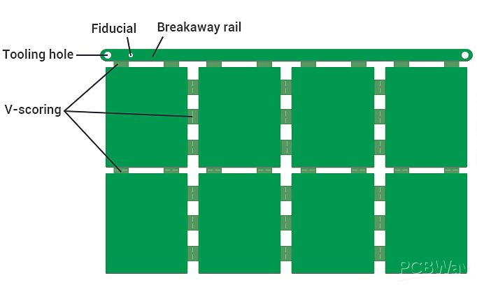
V-scoring, also known as V-grooving or V-cutting, is a method of separating two individual circuit boards by cutting "V"-shaped grooves on the top and bottom of a rigid board. Just like the indentations in a chocolate bar, there are grooves between different circuit boards. This will facilitate the separation and assembly of the circuit boards.

In PCB manufacturing, V-scoring is primarily used to assemble a group of PCB boards into a panel, aiming to improve the efficiency of PCB assembly. The idea behind V-scoring the circuit boards is to provide a sturdy support structure for the assembly process, allowing minimal pressure to be applied to the circuit boards when SMT machines place SMD components onto them and when separating the assembly panels. PCB panels enable PCB assembly manufacturers to load components at a faster pace since they can complete a panel at once instead of loading individual PCB boards one at a time. That is why PCB manufacturers, PCB customers, and assembly manufacturers are willing to use V-scoring for panelization.

The V-scoring process consists of two blades with arbitrary angles, such as 20°, 30°, 45°, and 60°. These blades function like wheels with many gears, and the gears are the knives used for scoring. One blade is positioned on the top, and the other on the bottom, rotating point-to-point, with a certain distance to allow the PCB board to pass through. This distance determines the remaining thickness between the two V-shaped cuts. The remaining thickness supports the subpanels or production panels that hold the PCB units together. Once the PCB board assembly process is completed, the subpanels are separated into individual PCB assembly boards.
V-shaped scoring lines are formed on the circuit board using precision cutting tools. Please adhere to the following rules:
V-scoring lines must be straight and either vertical or horizontal.
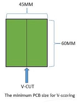
The minimum PCB size for V-scoring is 60mm*45mm, maximum size is 600mm*1200mm.


V-scoring angles: Available angles are 20°, 30°, 45°, and 60°. Generally choose 30°.

V-scoring angle tolerance: ±5°.
Alignment tolerance between upper and lower blades for V-scoring: ±0.05mm.
Tolerance for remaining thickness after V-scoring: Typically manufactured with a tolerance of ±0.10mm.
Control of remaining thickness: When the finished thickness is ≤1.0mm, the remaining thickness is generally set to 0.3mm.
When the final thickness is greater than 1.0mm, the remaining thickness is generally 1/3 of the board thickness. The minimum V-cut remaining thickness is 0.25+0.05/-0mm.
Minimum spacing for skip V-scoring: The minimum distance between skip cuts should be 5mm.
Breakaway rails should have a minimum width of 5mm.
We recommend using V-scoring only for board thicknesses greater than 0.6mm.
| V-CUT Parameter | Board Thickness | Remaining Thickness |
| H<0.60mm | 0.20mm | |
| 0.6mm≤H≤0.80mm | 0.35+/-0.10mm | |
| 0.80mm≤H≤1.60mm | 0.40+/-0.10mm | |
| H≥1.60mm | 0.50+/-0.13mm |
Next, let's learn more about panelization through the following video: